How to avoid the number one mistake when mounting a wrap spring clutch/brake
Wrap spring clutch/brakes are commonly found in a wide range of repeating industrial applications. For a single stop design, the unit will rotate 360 degrees and stop once for each signal. Repeatability is within a half degree and any error will not accumulate.
These features make wrap spring clutch/brakes excellent for applications that require the same movement every cycle. Common installations are on labelers, imprinters, die-cutters, staplers and index systems. In each case the unit must move the same distance every cycle.
One of the key challenges in using wrap spring clutch/brakes is that the unit mounting plate implies a method for mounting that is exactly wrong. All wrap spring clutch/brakes are designed with a rectangular backing plate that supports the actuator, the solenoid and the body of the clutch/brake. This basic design has been the standard since at least the early 1970s, so changing now would be a hardship for many customers.
In addition to supporting the clutch/brake mechanism, the backing plate serves as a torque arm for the unit. It keeps the unit from rotating. However, the rectangular design with the four holes implies that the unit should be mounted rigidly to the machine frame. Many customers do just that, and those customers experience poor unit performance and reduced clutch/brake life as a result. In fact, over 50% of non-wear wrap spring clutch/brake failures are related to incorrect mounting.
Rigid mounting of the back plate will have several negative impacts:
- Will cause binding between the ID of the brake hub and OD of the shaft.
- Will cause friction between the end of the hub and the mating face of the shaft which will transmit torque from hub to shaft, creating wear.
- May close the gap between hub OD and brake spring ID. The spacing between hubs and shaft are less than .010 inches; binding can close that gap.
Any of these may cause the clutch spring not to fully disengage when the clutch actuator engages the collar. The long and short of it is that a wrap spring clutch/brake, with the back plate rigidly mounted, will have reduced life and increased inaccuracy and may suffer from other performance misbehavior as well.
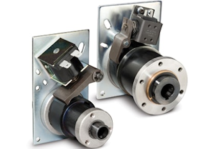
The ideal mounting scenario for a wrap spring clutch/brake is when the back plate is restrained from rotation, but is able to have slight axial movement. There are four holes in the plate that are used for plate location during assembly. For a size 6 unit, these holes are a 0.284 diameter. Simply mounting a .250 pin through one of those holes would meet the anti-rotation need. An alternative is to use the slot in the unit that is provided (Figure 1). A third solution is to use a piece of right angle metal, just off of the back plate that would keep the unit from rotating. Any of these three methods will work well and ensure maximum clutch/brake unit life.
A second area of concern is on the input hub side. Here, the impact of binding can be the same, but is often the result of excessive side loading from belt or chain drives. Best practice would be, wherever possible, to have a bearing under the sprocket or sheave so that it can absorb any side loading from the belt or chain as shown in Figure 2.
A properly installed wrap spring clutch/brake will provide millions of cycles for applications where repetitive motion is needed. Care to insure proper mounting will achieve the best possible life and performance in repeating applications.