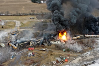
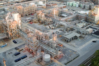
On the evening of April 20, 2010, Deepwater Horizon suffered a blowout while drilling in the Macondo Prospect, an area in the Gulf of Mexico 40 miles off the southeast coast of Louisiana. The platform caught fire; two days later, it sank. Numerous attempts were made to seal the well, but oil continued to spew into the Gulf until July 15, when a temporary cap was put in place. Relief wells then pumped concrete into the area underneath the wellhead, and the well was deemed permanently sealed in mid-September.
Investigating the cause of the blowout
Deepwater Horizon was a semi-submersible, dynamically positioned drilling platform, or mobile offshore drilling unit (MODU). In layman’s terms, it was a huge floating oil rig, capable of adjusting position under its own power, and designed to operate in water up to 8000 feet and drill wells nearly 6 miles deep.
Blowouts occur when pressurized oil and gas flow uncontrolled up the drill pipe or riser to the rig, posing extreme risk to the people operating the rig, as well as possible damage to the environment and the platform itself. To prevent this situation, modern rigs are equipped with blowout preventers, or BOP stacks, huge structures that sit on the sea floor directly over the wellhead (see image below). The drill pipe passes through the BOP stack, which contains a number of mechanisms—shear rams, bore rams, annular preventers, and a host of electronic and hydraulic assemblies—that are supposed to shut the well down safely in the event of a blowout.
During the initial event and in the weeks after Deepwater Horizon sank, numerous attempts were made to activate the BOP stack—initiation of the emergency disconnect sequence from the failing rig, automated dead-man circuitry on the BOP stack, even remotely operated vehicles working directly on the stack’s “autoshear” function, one mile down. Nothing stopped the flow of oil.
|
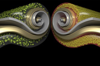
How FEA works Finite Element Analysis (FEA) is a widely accepted computer simulation methodology for modeling, evaluating, and/or optimizing a product’s mechanical and structural design. The technology has a long history of effective use within the energy industry as well as the aerospace and automotive sectors. Engineers generally start with a 3D CAD model—perhaps of an oilfield pipe installation, an airfoil, or the chassis of a car—and then use FEA software to transform that model into a 3D mesh of geometric units, which are the ‘elements’ in finite element analysis. Each element is assigned a distinct size and shape mathematically representing a finite section of the model. Linked together by nodes that quantify their interrelationship, the elements (which can number in the hundreds of thousands or even millions) are further constrained by boundary conditions, material characteristics, and a host of other inputs dictated by what type of product or structure is being modeled. Once an FEA model is set up, any number of static, dynamic, linear or nonlinear events, including contact, collisions, buckling and/or collapse scenarios, and even multiphysics analyses (thermal-structural, fluid structure interaction and/or computational fluid dynamics), can be simulated and analyzed. Feedback from the FEA solution (‘virtual testing’) can then be used to evaluate and modify the CAD design, repeatedly if necessary, until the desired product functionality and durability are reached. Alternatively—as in the case of the Deepwater Horizon accident—FEA can be employed in a retroactive way to forensically examine computer models derived from scans of damaged oil well components, in order to identify what kind of events may have caused the damage. |
The U.S. government moved quickly. Even while the oil industry was working to shut down the well and contain the spill, the Departments of Interior and Homeland Security signed an order to begin an investigation. In August, they released a competitive Request for Proposal (RFP) for an analysis of the BOP operation and failure to seal the well. On September 1, DET NORSKE VERITAS (U.S.A.), Inc., Columbus, Ohio office was awarded a contract to determine the performance and possible failure modes of the BOP stack. DNV pulled together an expert team of 40 individuals in forensic investigation, materials specialists, BOP operation, systems controls, and computer modeling from its Columbus, Ohio, Houston, Texas, and Høvik, Norway offices to address all issues involved in this multidisciplinary investigation.
DNV had a tall order. Their contract charged them with “determining the performance of the BOP system during the well control event, any failures that may have occurred, the sequence of events leading to failure(s) of the BOP….” To meet this challenge, the DNV team assembled a base of operations at NASA’s Michoud facility in New Orleans. The intervention vessel Q-4000 raised the BOP stack and delivered it to a temporary enclosure there. The investigation was underway.
Finite element analysis as a forensics tool
| Schematic view of the BOP stack seen from Deepwater Horizon’s port side. |
Shane Finneran, project engineer and team lead in the Computer Aided Engineering (CAE) Group at DNV’s Materials and Corrosion Technology Center, Dublin, Ohio, was a key player in the investigation. His team was involved throughout the Deepwater Horizon Blowout Preventer Forensic Examination, leading the 3D laser scanning and computer modeling initiatives and assisting with materials evaluation and damage assessment.
DNV faced the problem of quickly constructing and testing numerous computer models of the stack’s mechanical components. They turned to Abaqus FEA software (from SIMULIA, an application from Dassault Systèmes’ 3DEXPERIENCE technology), which has been part of DNV’s investigative toolkit for over a decade. [See Sidebar]
FEA provided DNV with a rapid, accurate methodology to simulate and evaluate the likelihood of proposed scenarios, many of which would have been difficult and impractical to assess with physical testing.
“It would be extremely difficult and generally cost prohibitive to run physical tests under the same conditions that exist two miles under the ocean, re-enacting a blowout scenario,” says Finneran. “Typical physical testing involves shearing pipe with no backpressure and no product flow. You’re proving that the blind shear ram can shear pipe and that the rams close properly. However, FEA can provide the means to perform extensive simulations of many types of damage—ranging from simplified deformation and buckling to post-buckling deformation and shearing—with realistic pressure and force measurements built into those simulations.”
A 200-page report published by DNV for the Department of the Interior’s Bureau of Ocean Energy Management, Regulation, and Enforcement (BOEMRE) (available at http://www.bsee.gov/uploadedFiles/DNVReportVolI.pdf) explains in great detail the reconstruction process and test methodology used by DNV, as well as their findings.
- The BOP stack, together with several pieces of drill pipe, was raised from the well site and transferred to a holding facility at NASA-Michoud.
- The team cleaned, photographed, and cataloged the stack, disassembling where necessary to get at its inner workings.
- Hydraulic fluids and metal samples were taken for analysis, the stack’s control mechanisms and their batteries, actuators, and solenoids were tested, and the casing and blind shear rams, variable bore rams, and upper and lower annular preventers were all visually inspected and 3D laser scanned.
- DNV then used the laser scans to construct as-is 3D CAD models of the damaged equipment, especially in the area of the BSR, the blind shear ram, which was the only ram on the BOP designed to cut the drill pipe and seal the well bore.
- SolidWorks software, also from Dassault Systèmes, was used to convert the original CAD files of the ram components into simplified surfaces for use with Abaqus FEA, enabling the team to simulate and virtually test their theories of what happened.