www.newson-gale.com Page 1 of 8
W
h
it
e
P
a
p
e
r
1. Static Grounding Benchmarks.
Before embarking on this guide to specifying and sourcing
static grounding solutions it should be asserted from the jump-
off point that Hazloc approved equipment that carries the mark
of an Nationally Recognised Testing Laboratory (NRTL), like UL,
FM or CSA, is not a validation of a grounding system’s
performance characteristics when it relates to providing static
grounding protection. Although a lot of time and effort can be
put into sourcing grounding solutions that match or exceed
your Class and Division requirements, the first recommendation
this buyer’s guide will make is to take account of Hazloc
industry associations that provide guidance on preventing
ignitions caused by static electricity. There are several
documents published by highly authoritative and respected
associations around the world that identify the industrial
processes that can be the source of electrostatic ignitions.
The committees that are assigned the task of developing and
updating these guidance documents in line with the latest state
of the art techniques are employees of companies and
consultancies active in the hazardous process industries.
Demonstrating compliance with the recommendations outlined
in these guidance documents will virtually ensure all of the
electrostatic hazards presented by your company’s operations
are under your control. If you can specify grounding solutions
that display compliance with the publications listed in Table 1,
you will be ensuring your static grounding protection methods
display the latest state of the art in preventing fires and
explosions caused by static electricity.
An Industrial Buyer’s Guide to
Protecting against the Ignition
Hazards of Static Electricity.
Hazop assessments, and the reports that follow on from them, are a great way of capturing and identifying processes and
practices that could lead to the ignition of flammable atmospheres through discharges of static electricity. What Hazop reports
are not so great at doing is identifying what the grounding solution to eliminate the risk should look like.
The task of identifying the right grounding solution falls to people like you and members of your team and it’s not likely to be something
you deal with on a day to day basis. For most people, identifying and specifying the right static grounding solution is probably the kind of
project they’ll handle once or twice in their career. But get it right first time and it quickly becomes an area where you can bring value to the
table throughout your career. This guide is about helping you get started on the right path and can be best described as a door opener to
the subject of hazardous location static control.
The guide is broken down into three distinct sections. The first section deals with industry guidelines that provide guidance on controlling
static electricity in hazardous locations. The second section helps you work out the “best-fit” for controlling electrostatic hazards at your
site and the third section touches on Hazloc equipment approvals, specifically what you should be looking for when selecting a Hazloc
approved static grounding solution.
Author Details:
Mike O’Brien, Managing Director for Newson Gale
If you have any questions relating to the topics discussed
in this article, please contact .Newson Gale
Inquiry > Click here to submit a
product related query or a request
for quotation.
www.newson-gale.com
The guidelines in Table 1 describe how and why certain
operations, whether it involves liquids, gases or powders, can
generate static electricity and result in the static electricity
accumulating on the equipment being used in the process. The
primary means of preventing ignitions caused by static
electricity is to ensure all conductive and semi-conductive
equipment, including people, are bonded and grounded to a
verified “true earth” grounding point. This ensures electrostatic
charges cannot accumulate on equipment and discharge a
spark into an ignitable atmosphere.
Because the Earth has an infinite capacity to balance positive
and negative charge, if equipment is connected to it, that
equipment is at “ground potential” meaning it can’t charge up in
response to static generated by the movement of material. The
National Electrical Code describes a connection to the general
mass of earth as a “true earth ground”.
Just as many other safety related functions have benchmarks
designed with factors of safety in mind, grounding and bonding
circuits can, and should, work to benchmarks that exceed the
minimum safety requirements. The minimum theoretical
requirement for grounding electrostatic charges is usually
described in academic circles as having an electrical resistance
not exceeding 1 meg-ohm (1 million ohms) between the object
at risk of charge accumulation and the general mass of earth.
However, it is well recognised that metal objects at risk of
charge accumulation, e.g. tank trucks, and the grounding and
bonding circuits providing grounding protection, should never
display an electrical resistance of more than 10 ohms if they are
in good condition. This value of 10 ohms is the one value of
resistance that is consistently recommended across all of the
publications listed in Table 1. So wherever a grounding solution
is being sourced for operations that involve metal objects like
tank trucks, railcars, totes, barrels and containers, grounding
systems that display ground monitoring values of 10 ohms or
less should be specified.
Another reason why the theoretical value of 1 meg-ohm does
not have a role in real world applications is the requirements
related to grounding Type C FIBCs (Super-Sacks). Although
CLC/TR: 50404 (2003) states that the resistance through a Type
C FIBC bag should not exceed 100 meg-ohm, the latest state of
the art guidance published in IEC 60079-32-1 (2013) and NFPA
77 (2014) states that resistance through the bag should not
exceed 10 meg-ohm.
Page 2 of 8
An Industrial Buyer’s Guide to
Protecting against the Ignition
Hazards of Static Electricity.
Association Publication Title Listed by Year of
Publication
National Fire Protection
Association
NFPA 77: Recommended Practice on Static Electricity 2014
International Electrotechnical
Commission.
IEC 60079-32-1: Explosive Atmospheres Part 32-1:
Electrostatic Hazards - Guidance.
2013
American Petroleum
Institute
API RP 2003: Protection Against Ignitions Arising out of Static,
Lightning, and Stray Currents, Seventh Edition.
2008
CENELEC CLC/TR 50404: Electrostatics - Code of Practice for the
Avoidance of Hazards due to Static Electricity. Superceded by:
CLC/TR 60079-32-1: Explosive atmospheres - Part 32-1:
Electrostatic hazards, guidance.
2003
2015
Table 1: Hazloc industry guidelines for preventing fires and explosion caused by static electricity.
Concentric Shells
of Resistance to
Earth (red shells)
True Earth
Grounding Point
EARTH
Fig. 1: to ensure equipment cannot accumulate electrostatic charge,
the equipment should be connected to the general mass of the earth
by means of a true earth grounding point. The resistance between
the grounding point and true earth must be low enough to allow the
electrostatic charge generated by the process flow to earth.
www.newson-gale.com
So clearly, a “theoretically acceptable” value of 1 meg-ohm is
impractical when discussed in the context of metal objects that
should display a benchmark resistance of 0 to 10 ohms , and
Type C FIBCs that should display benchmarks of either 0 to 10
meg-ohm or 0 to 100 meg-ohms (depending on what standard
the bag is manufactured to).
NOTE: If you are engaged in sourcing a grounding solution for
Type C FIBC bags you must ensure you know what standard the
bags are manufactured to. If you don’t know what standard your
bags are manufactured to the bag supplier should be
consulted. Once you know what standard your bag is
manufactured to you should source a Type C FIBC grounding
system that monitors the grounding circuit from 0 ohms up to 10
meg-ohms (NFPA 77 / IEC 60079-32 compliant) or from 0 ohms
up to 100 meg-ohms (CLC/TR: 50404 compliant). Avoid
grounding systems that do not monitor the full range of
resistance as they are likely to fail bags that are designed to
work up to 100 meg-ohms and pass bags that should only work
up to 10 meg-ohms.
2. Source a grounding solution that provides the
“Best Fit” with your objectives.
Your company’s Hazop report will normally identify the risk of
static sparks from specific equipment like tank trucks, barrels,
totes, etc., and provide an assessment of what impact a fire or
explosion caused by an electrostatic ignition could have on the
area. It will be your task to determine what the grounding
solution needs to look like. Before fully embarking on the search
for a static grounding solution, determine the layers of
protection you want from an electrostatic ignition hazard. The
more layers deployed to protect against an ignition source, the
more likely static will controlled in a safe, repeatable and reliable
way.
Producing answers to the following questions will help you
identify the layers of protection you require from your static
grounding solution.
A. Who will be responsible for ensuring the equipment is
grounded prior to, and during, the operation and how do we
alert them to a situation where there could be an
electrostatic discharge risk?
B. If, for whatever reason, the equipment loses its grounding
protection during the operation, do I want that process to
continue building up electrostatic charge on the
equipment?
C. What type of equipment requires static grounding protection
and does the application have unique characteristics that
require a particular type of grounding solution?
2.1 Assessing the required Layers of Protection
in the context of Question A:
With the exception of locations like laboratories that handle
small quantities of flammable products, the act of grounding a
piece of equipment identified as being a static discharge risk
will be the responsibility of equipment operators, or in the case
of tank truck and vacuum truck operations, the driver of the
vehicle. Because static electricity is a complex technical subject
(some would even say akin to witchcraft!) it can be hard for
people who don’t deal with it on a day-to-day basis to grasp the
fundamentals of why it is a serious risk when assessed in the
context of operations conducted in flammable atmospheres. An
unhealthy paradigm of it “can’t happen to me” can follow on
from this lack of awareness especially when the hazard is
neither a tangible nor visual risk that would trigger a natural
safety related response from an individual.
Page 3 of 8
Fig. 2: pulsing green ground status indicators provide operators with
a visual reference point to ensure the equipment they are operating is
grounded prior to, and during, the operation.
An Industrial Buyer’s Guide to
Protecting against the Ignition
Hazards of Static Electricity.
www.newson-gale.com
As static electricity is neither a visible nor tangible hazard the
main challenge is to get your company’s operators to take
responsibility for their own safety and the safety of their
colleagues. The most effective way of getting operators into the
habit of grounding equipment on a routine basis is to deploy a
grounding solution that requires a visual confirmation of a
verified ground before the operation can start. If the operator
has a visual reference point for knowing when the operation can
begin, they can be trained to take responsibility for the action of
grounding the equipment they are operating. The most effective
method of indication is to use green indicators to communicate
a “GO” situation and red indicators to communicate a “NO GO”
situation. To really get their attention, pulsing LEDs can prove
very effective at telling the operator that the resistance in the
grounding circuit is being monitored on a continuous basis and
that he/she needs to see a pulsing green light before, and
throughout, the operation.
Some grounding solutions have in-built buzzers that can alert
operators to a lost grounding connection, however, you do
need to be careful when evaluating such equipment, as the
audibility of the buzzers frequently become redundant when
they are competing against the ambient noise levels of the
immediate working environment, if the operator is out of the
buzzer’s effective audible range or if the operator must wear ear
mufflers or protective ear plugs.
The benchmarks that should be in place to monitor grounding
and bonding circuits should be based on the guidance outlined
in the publications listed in Table 1. This will ensure your
grounding solutions, hence your company, displays
compliance with the leading authorities and latest state of the art
in static grounding protection. Just to recap, any equipment of
metallic construction like tank trucks, railcars, IBCs, drums and
powder processing systems should be monitored with a
resistance not exceeding 10 ohms back to a verified earth
grounding point. Type C bags manufactured in line with IEC and
NFPA requirements should be monitored with 10 meg-ohm
grounding systems and Type C bags manufactured to
CENELEC requirements should be monitored with 100 meg-
ohm grounding systems.
2.2 Assessing the required Layers of Protection
in the context of Question B:
Visual indication and continuous ground circuit monitoring are
two fundamental layers of protection that tend to go hand in
hand. However, when there is no active grounding of the
equipment and the operation is still running (thereby rapidly
accumulating hazardous static charges) there must be
additional controls in place that will prevent the equipment from
rapidly accumulating hazardous electrostatic charges. Shutting
down the movement of the material being processed will stop
the generation of static electricity.
A common action is for the equipment operator to hit an
emergency shutdown button to prevent further generation and
accumulation of static electricity on the equipment he/she is
operating. Depending on the nature of the operation, and with
the best will in the world, people’s attention can, and will, be
diverted to other activities while the operation is running so in
the event that grounding or bonding is lost an additional layer of
protection that can be deployed is to shut down the operation
automatically.
Automatic shutdown can be achieved with grounding systems
that carry output contacts which can be interlocked with a range
of devices (switches, valves, PLCs) that can execute a
shutdown in response to the monitoring circuit identifying a lost
ground connection. Visual indication is an effective layer of
protection to get grounding in place before the process is
started by the operator and interlocks are an additional layer of
protection that ensure that an automatic shutdown, as opposed
to a manual shutdown, prevents the rapid build-up of static
electricity.
2.3 Assessing the required Layers of Protection
in the context of Question C:
As highlighted already, there are many operations carried out in
the hazardous process industries that require static grounding
protection but the nature of the operation and the environments
they are conducted in can vary greatly. Different Class and
Division requirements coupled with the characteristics of the
operation and the scale of the hazard, particularly the amount of
flammable or combustible material at risk of ignition, can
influence the kind of solution specified.
Page 4 of 8
An Industrial Buyer’s Guide to
Protecting against the Ignition
Hazards of Static Electricity.
www.newson-gale.com
This generally means that a “one-size-fits-all” off-the shelf
grounding solution will not provide you with the layers of
protection and installation flexibility you may require. The
following examples help illustrate how different processes can
have unique characteristics that can influence the type of
grounding solution employed by your company.
2.3.1 Drumming operations require the repeated filling of
drums on a continuous basis where the drums can be filled with
fixed pumps that can fill four drums to a pallet, can be filled with
fixed pumps on a rolling conveyor system or can be filled with
portable pumps. Because such operations are typically carried
out indoors, a number of HazLoc locations ranging from
Division 1 locations right through to Non-Hazardous locations
could reflect a matrix of installation options and required layers
of protection that provide the best fit for your static grounding
application.
Page 5 of 8
Imagine a scenario where up to 10 drums can be filled with
portable pumps at a dedicated solvent filling location at any one
time. Because the pumps are held by the operators and require
the operators to continuously “eyeball” the liquid level in the
drum, when management analyse the trade-off between
interlocking the pumps with that of a manual shutdown by the
worker operating the pump, they deem it OK for the operator to
both start and stop the pump in response to a visual indication
of each drum’s ground connection. An ancillary benefit of
determining this operation’s required layers of protection,
which is ground circuit monitoring in combination with a visual
I.D. of the ground status of the drum, is that a solution like the
Bond ®-Rite REMOTE can be specified to monitor multiple
drums off a single power supply on a 24/7 basis.
The benefit of this type of solution is that it closes the gap
between no visual indication via “passive” grounding clamps
and “off-the-shelf” grounding solutions with interlocks that
require a 110 V AC line supply or 24 V DC supply delivered to 10
separate grounding systems operating in the hazardous
location. A solution like the , which only Bond ®-Rite REMOTE
requires a single 110 V AC or 24 V DC feed to its Class 1, Div. 2
mounted power supply, can deliver Intrinsically Safe power to
the 10 Class 1, Div. 1 ground status indicators, which can then
independently monitor the grounding status of each individual
drum. If filling is carried out on a less routine basis, installation
time can be reduced by specifying ground status indicators that
are powered by their own internal battery.
Fig. 3: pulsing green ground status indicators provide operators with a visual reference point to ensure
the equipment they are operating is grounded prior to, and during, the operation.
Class 1 Div.2
Class 1 Div.1
HazLoc power
supply
Ground Status
Indicator Stations
An Industrial Buyer’s Guide to
Protecting against the Ignition
Hazards of Static Electricity.
www.newson-gale.com
2.3.2 Vacuum trucks provide a multitude of services to the
hazardous process industries, with the primary role of cleaning
out storage tanks and sucking up spills from loss of
containment incidents. They also present one of the most
complex problems in terms of assigning layers of protection that
can control an electrostatic hazard in a safe and repeatable way.
They process and transport large quantities of volatile
flammable liquids and powders, often in less than perfect
circumstances when it comes to controlling the presence of
flammable atmospheres.
They operate in many different locations, often in a remote
setting, where there will be no ground monitoring systems in
place for them to connect to and the speed at which material is
transferred, which increases the rate of charge generation, can
be very high. In short, the risk profile is pretty high and until
recently all drivers could do was connect a passive grounding
clamp to a metal object, like a tank shell, or piping, in the hope
that he/she could ground the truck safely and reliably, without
monitoring the grounding circuit or even knowing if the object
he/she connected the clamp to had a verified true earth ground
connection (see Fig. 1).
Page 6 of 8
Fig. 4: vacuum trucks operate in multitude of environments ranging
from Class 1 Div. 1 locations right through to non-hazardous locations.
Providing the right layers of protection from and electrostatic spark
can be a significant challenge.
An Industrial Buyer’s Guide to
Protecting against the Ignition
Hazards of Static Electricity.
Nowadays, vacuum truck service providers and their clients
can specify truck mounted grounding systems that will verify a
connection to true earth; monitor the connection constantly,
provide a visual indication of a verified ground to the driver and
automatically shut down the operation if the ground connection
is lost during the transfer. Due to the risk profile of this type of
operation a solution like the can provide the Earth ®-Rite MGV
maximum layers of protection by ensuring:
1) The grounding point the truck is connected to IS
connected to the general mass of the earth.
2) The driver has a visual indication of a good static ground
connection so he can carry on with the job at hand.
3) The ground path between the truck and the verified
grounding point is continuously monitored to 10 ohms.
4) A pair of output contacts can shut down the transfer
operation if the ground connection is lost especially when
the driver does not have a consistent view of the ground
status indicators.
Class I, Div.2
Class I, Div 1
To select the solution that provides the best-fit, source solutions
that can combine the features outlined in the columns of Fig. 6.
Starting at the most basic level, you should avoid using devices
like welding clamps and alligator clips as these devices are not
designed with static grounding in mind, especially for the kinds
of processes that require the penetration of an insulating layer
like a paint coating or rust. Static grounding clamps should be
subjected to FM testing to ensure they are suitable to use in
hazardous locations. Following on from this, the grounding
solution specified should combine the features outlined in
Fig. 6.
www.newson-gale.com Page 7 of 8
Fig. 6: Grounding solutions can be selected based the layers of
protection you require from the risk of an electrostatic ignition.
An Industrial Buyer’s Guide to
Protecting against the Ignition
Hazards of Static Electricity.
ATEX / FM approved
grounding clamps
Continuous Monitoring
of the equipment’s
ground resistance
Operator Indication of
when grounding is
present or lost
ATEX / FM approved
grounding clamps
Continuous Monitoring
of the equipment’s
ground resistance
Operator Indication of
when grounding is
present or lost
Interlocks that
initiate automatic
shutdown
Road Tanker
Truck Recognition
True Earth Ground
Verication
ATEX / FM approved
grounding clamps
Continuous Monitoring
of the equipment’s
ground resistance
ATEX / FM approved
grounding clamps
Continuous Monitoring
of the equipment’s
ground resistance
Operator Indication of
when grounding is
present or lost
Interlocks that
initiate automatic
shutdown
ATEX / FM approved
grounding clamps
+
Increased Control Over Electrostatic Ignition Risk >
5
4
3
2
1
Fig. 5: A truck mounted static ground verification system with interlock
control of the vacuuming operation reduces the electrostatic ignition
risk profile of vacuum truck operations by a significant margin.
N
G
U
S
W
h
it
e
P
a
p
e
r
2
9
2
6
0
9
1
8
3. Selecting Hazardous Location Approved
equipment:
It’s no easy task sourcing grounding equipment that complies
with your company’s Hazloc Class and Division or Class and
Zoning requirements and is a subject that could fill a buyer’s
guide in its own right. There is just one area worth mentioning in
terms of selecting a grounding solution: try to source grounding
equipment that has been approved to standards that reflect the
latest state of the art in respect of Hazloc “equipment protection
techniques” in accordance with the National Electrical Code.
There are many Hazloc approved devices, not just grounding
devices, on the market today that have been approved to
standards that have gone through several revisions, or are no
longer in existence, since the devices were first approved. For
example, the standard that is used to assess whether or not
electrical equipment complies with the requirements of the
National Electrical Code in respect of Intrinsic Safety, UL
standard 913, has been through two revisions since 1997. If
grounding systems approved prior to this date were assessed
by an NRTL today, it is very probable that the device would need
to be redesigned to match the requirements of UL 913 today.
Summary:
This guide will hopefully have provided you with enough
information to get you started on the right path to buying static
grounding solutions that best fits your company’s operations
and their risk profile. The foundations of your buying
specification should be built on:
Sourcing static grounding equipment that can demonstrate Ÿ
compliance with the latest state of art in static control,
namely, NFPA 77, API RP 2003, IEC 60079-32 or CLC/TR:
60079-32-1.
Determining the layers of protection you think will control Ÿ
the risk of an electrostatic ignition – this will help you identify
a grounding solution that will provide the “best-fit” for your
operations and your operators.
A company that truly specialise in static grounding protection
should be contacted to help guide you through this process.
Newson Gale has offices in the U.S., Europe and South East
Asia with teams that are on hand to help you navigate your way
to the right static grounding solution. Why not contact one of
our offices today to get you started on the right path?
An Industrial Buyer’s Guide to
Protecting against the Ignition
Hazards of Static Electricity.
www.newson-gale.com
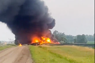
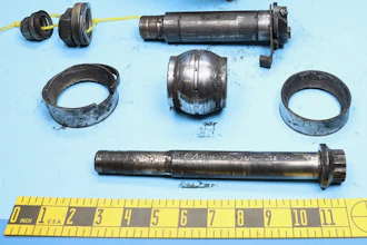
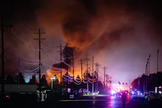
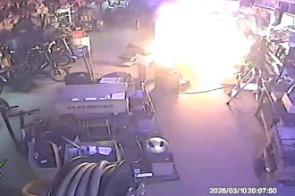
Examples of how different operations can result in discharges of static electricity:
It’s worth noting that the common denominator in these incidents was that the operator(s) did not have a visual reference point for a
verified ground connection.
news.bbc.co.uk/1/hi/england/nottinghamshire/8506055.stm
www.csb.gov/barton-solvents-flammable-liquid-explosion-and-fire/
United Kingdom
Newson Gale Ltd
Omega House
Private Road 8
Colwick, Nottingham
NG4 2JX, UK
+44 (0)115 940 7500
[email protected]
Deutschland
IEP Technologies GmbH
Kaiserswerther Str. 85C
40878 Ratingen
Germany
+49 (0)2102 5889 0
[email protected]
South East Asia
Newson Gale S.E.A. Pte Ltd
136 Joo Seng Road, #03-01
Singapore
368360
+65 6704 9461
[email protected]
United States
IEP Technologies, LLC
417-1 South Street
Marlborough, MA 01752
USA
+1 732 961 7610
[email protected]
An Industrial Buyer’s Guide to Protecting against the Ignition Hazards of Static Electricity
Hazop assessments, and the reports that follow on from them, are a great way of capturing and identifying processes and practices that could lead to the ignition of flammable atmospheres through discharges of static electricity. What Hazop reports are not so great at doing is identifying what the grounding solution to eliminate the risk should look like.
Latest in Safety

Sponsored

Shadow 10 Light Curtain
July 6, 2026


Fill out the form below to request more information about An Industrial Buyer’s Guide to Protecting against the Ignition Hazards of Static Electricity