This article first appeared in IMPO's September 2013 issue.
A typical manufacturing plant today will have thousands, or even many thousands, of electrical connections on both fixed equipment and moving machines. And it’s just a matter of time before some of those connections fail or wear out, bringing production machines to a dead stop. One way to minimize this downtime is to “connectorize” power and signal cables. Multi-conductor cables can often be replaced in just minutes if they have connectors at both ends. Hard-wiring that same cable could take hours.
Connectors Prevent Downtime
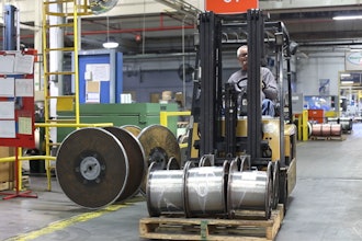
Power and signal disruptions have many mechanical and electrical causes, everything from forklift accidents to overcurrent conditions. With all the mission-critical electrical connections in a modern plant, downtime from damaged electrical connections is a matter of “when,” not “if.”
Think of connectors as a low-cost insurance policy against this downtime. While connectors do add a small premium to the initial cost of cabling, they will pay for themselves many times over if they eliminate even a few minutes of downtime on a busy production line.
Connector Selection Made Easy
For all their downtime-prevention benefits, there is one problem with connectors — call it “connector confusion.” There are currently dozens of connector varieties and thousands of individual connectors on the market, and even experienced engineers can find it difficult to select the right connector for the job at hand.
Fortunately, connector confusion can be minimized by gathering information on four key technical factors. This information is readily available to any engineer who has already sized the application’s power or signal cables:
Number of contacts. It may seem obvious that the number of contacts in the connector should match or exceed the number in the cable. But one common mistake is to miscount by not considering the ground. Cable conductor counts typically include ground while connectors do not.
Wire gauge (AWG). Cable’s wire gauge needs to be within the allowed range of the connector contacts. In general, screw contacts will accommodate a broader range of wire gauges than comparable crimped contacts.
Cable outside diameter (OD). This fundamental piece of dimensional information is too often overlooked during the specification process. Forgetting OD can have serious consequences. If the OD of the cable is too small relative to the housing, a poor seal will result, creating a performance issue. If the OD is too big, the cable may not fit in the housing easily or at all, creating a potentially costly installation issue.
Maximum voltage and current. Always double check to make sure the application’s voltage and current are within the rated capacity of the connector. For safety’s sake, this is the cardinal rule of specifying connectors.
Taken together, these factors determine whether the connector will function as a true extension of a given cable. It’s important to emphasize that all four factors must be taken into consideration.
A connector, for instance, may meet the requirements on number of contacts, wire gauge, and outside diameter but not satisfy the application’s current or voltage requirements.
The four key connector factors should be thought of as a starting point. They don’t capture the effects of difficult operating environments or unusual electrical requirements, but will help you quickly narrow down the field of connector products.


