 Fig. 1. Workers stand next to the Silo 3 packaging systems. On system #1 is a Lift-liner package inside a loading frame prepared to be loaded. Fig. 1. Workers stand next to the Silo 3 packaging systems. On system #1 is a Lift-liner package inside a loading frame prepared to be loaded. |
New packaging options offer more transportation strategies By Kenneth M. Grumski Abstract The Fernald Closure Project (FCP), formerly known as the Fernald Environmental Management Project (FEMP) and the Feed Materials Production Center, is a 1,050-acre Department of Energy (DOE) facility located approximately 18 miles northwest of Cincinnati. Fernald, Ohio is a small rural community located just south of the FCP. The FCP is a government-owned facility that operated from 1952 to 1989, providing in excess of 500 million pounds of high-purity uranium metal products in support of U.S. Defense initiatives. In 1992, the site was renamed the Fernald Environmental Management Project and the mission was formally changed to environmental restoration under the Comprehensive Environmental Response, Compensation, and Liability Act (CERCLA), commonly known as Superfund. Its current name, the Fernald Closure Project, was adopted in 2003 to reflect a continuing emphasis on the completion of restoration activities and achieving the final closure end state safely and efficiently. Silo 3, located on the western periphery of the site, is an unbermed concrete silo that contains approximately 5,088 cubic yards of cold metal oxides, a by-product material generated during Fernald’s uranium processing operations. The materials contained in Silo 3 consist of relatively dry, powder-like residues that were placed in the silo from 1954 to 1957. The residues consist of the metallic and non-metallic impurities that remained following the extraction of uranium from ore and ore concentrates in Fernald’s refinery operations during the mid-1950s. The residues were prepared for storage following a volume reduction and concentration step known as calcining, which is a roasting process in the presence of lime that serves to remove moisture and convert the impurities to their more stable (less leachable) oxide form. Following calcining, the dry residues were pneumatically conveyed to Silo 3 for longer-term interim storage as part of DOE’s ongoing custodial responsibility for the materials. The Silo 3 residues are designated as Section 11e.(2) byproduct materials under the Atomic Energy Act of 1954, as amended. As 11e.(2) byproduct materials, the residues are statutorily excluded from the definition of solid and hazardous waste under the Resource Conservation and Recovery Act (RCRA). Although Silo 3 material is statutorily excluded from formal RCRA hazardous waste definitions and administrative requirements, the Silo 3 residues do contain sufficient quantities of four RCRA regulated metals (arsenic, cadmium, chromium, and selenium) such that they can exceed RCRA thresholds for leachability as measured through the RCRA TCLP laboratory test. The predominant radionuclide of concern identified within the material is thorium-230, which is produced from the natural decay of uranium-238. The overall objective of the Silo 3 remedial action is to safely retrieve the residues from the concrete silo by both pneumatic and mechanical processes, condition the waste to reduce its dispersability and reduce leachability of RCRA heavy metals and package and transport the materials for off-site disposal. MHF-LS was contracted by Fluor Fernald to provide the mechanic packaging handling system, the software operating system and US Department of Transportation (USDOT) specified packaging to remove the Silo 3 material. This paper provides details on all aspects of the project. The package handling system utilized “off the shelf” components that were customized to create a virtually dust-free environment for the packaging radioactive materials. The system was designed in accordance with the Conveyor Equipment Manufacturer Associations (CEMA) requirements. All pneumatic components were UL rated and meet the standards set fourth by the National Fluid Power Association (NFPA). All electrical devices were designed in accordance with the National Electric Manufacturer Association (NEMA) requirements. The entire system met Fluor Fernald’s Quality Level 3 requirements. As part of the packaging system contract, MHF-LS also designed, tested and supplied approximately 2,000, USDOT IP-2 Lift-Liner container systems, in which extensive usage and research was performed. Assuring Fluor Fernald procured USDOT IP-2 tested soft-sided containers that have past performance qualities as specified in the contract.
 Fiq. 2. The Lift-liner system in the loading frame is power conveyed to the load position. Fiq. 2. The Lift-liner system in the loading frame is power conveyed to the load position. |
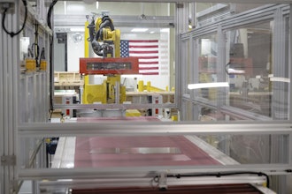
Introduction The Fernald Silo 3 Packaging System was a unique procurement in that the packaging system design and fabrication was “bundle together” with the procurement of the USDOT IP-2 packaging for the Silo 3 material. This made it difficult for vendors to bid since the two products were very diverse. MHF-LS was successful in the contract award because they teamed with a highly technical bulk packaging fabricator, B.E.S.T Inc., Brunswick, OH, and provided a proposal that exactly matched the request for proposal requirements. MHF-LS took the lead on the project since the project scope revolved around the IP-2 packaging and MHF-LS has had years of experience in working with the Department of Energy. MHF-LS is an American-based small business located near Pittsburgh, PA, specializing in the design and implementation of packaging and transportation programs. The firm was founded on the basic principal of providing innovative systems utilizing direct rail transport and intermodal systems that combine intermodal rail, truck, and marine conveyance systems. MHF-LS utilizes specialty equipment to transport chemicals, commodities, machinery, overweight or oversize components, raw materials, radioactive materials and wastes of all types including hazardous, non-hazardous and municipal. B.E.S.T. Inc. is a diversified manufacturer of custom-designed vibratory bulk process equipment who also provides a complete line of air and electric vibrators for all types of industry. MHF-LS/B.E.S.T. provided two packaging systems complete with all equipment, accessories and controls necessary for operation. Packaging systems for Silo 3 materials are to be used to dispense the material that is retrieved from Silo 3 into IP-2 96 cu ft Lift-liners. The contents of Silo 3 are a radioactive (1-5 mrem/hour), powdery material composed mainly of metal oxides. The material is very fine with up to 10 percent in the submicron range. The material is very dusty and similar to fly ash. Each packaging system was comprised of a package bulk bag loading stand, loading spout with components to allow height adjustment and water spray, vibratory densifier for deaerating of the bags, weighing system, container level measurement by weight and motorized roller conveyor sections for transporting the material away from the package loading stand to the cargo container bay. Below provides a detailed description of the system on a component basis. MHF-LS/B.E.S.T. integrated all components into each packaging system to allow enhancement of processing rates, minimization of exposure, and minimization of labor costs. Each system included the following major components: • Bulk bag loader • Package loading stands • Vibratory densification • Power roller conveyer • Bag inflation blower • Load cells/scales • Weight indicator • Inflation blower • Deaeration system, during fill • Flap valve • Heat sealer • Exit power conveyers • Other control/PLC components necessary for reliable and safe operation The design criteria was set to fill, settle, densify and weigh bulk bags in frames. Package container size is approximately 4 ft x 6 ft x 4 ft high. The maximum design load is 10,000 lbs, normal is 8,000 lbs. The product to be loaded was defined at low-level radioactive metal oxide powder - at approximately 25-40 lbs/cu ft (varies).
 Fig. 3. Operator positions RF seal arm into position for liner closure. Fig. 3. Operator positions RF seal arm into position for liner closure. |
Basic Bulk Bag Loader A four-post design was manufactured from 4 in. square, ¼ in. wall structural tubing. A double inflatable bladder type fill head was provided to insure as dust-free as possible operation at the bag spout. A concentric dust collection type infeed nozzle with 3 in. diameter dust take-off for removal of entrapped air in product while being loaded and compacted was also provided. The fill head also integrated a Jacobs engineered spray nozzle that allowed water to be added to the package as needed. This water feature enables cleaning of the interior of the fill head following the final package loading. Vertically adjustable fill head and pin type pneumatic auto loop release, provide the bag loop pressure release feature.
Package Loading Stands The processing rate for the packaging systems is approximately 6 cubic yards/hour or roughly seven tons per hour. The package-loading stands are equipped with lifting devices appropriate to lift and install the equipment.
Vibratory Densifier, Electric Powered Rotary Electric Motor powered Vibratory Grid Deck Table with airmount isolation. • Deck is approximately 54 in. wide x 84 in. long. • Chain-driven live roller deck above densifier will have rollers 3½ in. in diameter on approximate 9 in. centers. • Twin rotary electric motor vibrators, 5,280 lbs force each • 1200 RPM, 460 V, 3 Ph., 60 Hz., 2 HP motor • Air mount lift and isolation system complete with air controls • Designed for use with roller conveyor type decks • Grids lift load off roller conveyor during the vibration period • Resist-abrade liners on grids, 3/8 in. thick bolt-on, (non-conductive) 90 durometer rubber provides an anti-slip noise reducing medium between vibrating deck and metal container • Includes AC Inverter, variable speed Allen Bradley controller with overload protection, mounted in master control panel
 Fig. 4. The Lift-liner system is power conveyed out from loading area through a door airlock and position for final closure. Fig. 4. The Lift-liner system is power conveyed out from loading area through a door airlock and position for final closure. |
Powered Roller Conveyor • Chain-driven live roller conveyor • 54 in. wide x 96 in. long • 3½ in. diameter rollers on 9-in. centers • 30 ft/min conveying speed • mounted to BBL lower support structure • 1½ HP, 460V, 3 Ph., 60 Hz. • Motor starter included and mounted in master control panel
Load Cell Scale • Electronic load cell scale comprised of four tank type heavy-duty Sensortronics load cells, 3,000-lb capacity each, 12,000-lb capacity total • Machine usable capacity of 10,000 lbs • Completely wired to load cell summing box • Toledo Panther Digital Batch Type Weight Indicator with Allen Bradley remote I/O interface
Inflation Blower • An inflation blower was provided to pre-inflate bag prior to filling • All controls were designed for quiet/safe operation
Flap Valve • Air-operated, diverter flap valve, as an added option to (IB) package above, allowing hookup to customer’s dust collector in the field. Flap valve allows inflation first, then diverts air flow to dust collection side for entrapped air removal • Complete with solenoid valve and control software
 Fig. 5 The Lift-liner system is lifted out of load frame to be closed and prepared for shipment. Fig. 5 The Lift-liner system is lifted out of load frame to be closed and prepared for shipment. |
Heat Sealer In order to provide a wide seal that can be easily cut through and assure a 100% sealed surface on both ends of the PVC, Cosmos Electronic Machine Corp. fabricated a customized seal device that was integrated into the packaging system. The seal is a Radio Frequency (RF) seal that does not melt the PVC but instead bonds the two layers together by combining the two surface areas, creating a commingled seal. The seal is one-in. wide on each side of the perforation, continuously sealed across the filling spout. The seal assures a leak-proof package and a seal spout, until the next liner can be placed over the spout. The following is a description of the Radio Frequency Seal process: Cosmos 20KW rated RF generator with coaxial feed and pneumatically operated press is positioned to clamp around the neck of a waste bag. This (tear-seal) seals off both the entrance to the bag and the exit from the injection pipe simultaneously. Then with the use of a simple tearing action, the two parts can be separated. The equipment includes a state-of-the-art, real-time, automatic power control. The control monitors the RF energy and adjusts it in real-time, attempting to give a specific RF seal regardless of changes in the load. If for some reason, the RF seal should fall outside the set parameters, the operator is notified.
Exit Powered Roller Conveyors Four Additional Powered Roller Conveyors • Chain-driven live roller conveyors • 54 in. x 120 in. long • 3.5-in. diameter rollers on 9-in. centers • 30 ft/min conveying speed • Mounted to lower support structure with adjustable legs • ¾ HP, 460V, 3PH, 60HZ • Motor starter for each included and mounted in master control panel Roller conveyors were fitted with electric eyes for container positioning.
 Fig. 6. Control Panel Hardware (actual operator screen shot of system operation) Fig. 6. Control Panel Hardware (actual operator screen shot of system operation) |
PLC Components and Programming MHF-LS/B.E.S.T. developed the PLC software to provide the functional control and monitoring of the process. The annotated ladder diagram, along with the interface, became the controlling documents for describing the detailed sequence of the operation. The Panel View prompts the operator to input the following data: • Bag weight amount input, storage and recall • Operator inputted number of vibration cycles per filling sequence • Operator inputted vibration cycle times • One time entry of “bin” data, this feature allows the operator to input dribble and preact values for the fill device • Water washdown intervals and wash time • Manual override control of each component • User-friendly environment with easily understood user prompts The PLC software provides the operators full awareness of the entire systems operability including fire, ventilation and airlock conditions. The system can be controlled through touch screens both at the packaging point and remotely in the control room. The control panel was fabricated to the highest standards. The wires were tagged at both ends, neatly bundled and routed efficiently. Every effort was made to make the field-wiring connections as easy as possible. The panel was constructed with a NEMA 4/12 enclosure and all the components carried a U.L listing.
Silo-3 IP-2 Packaging The second part of the project was to provide USDOT packaging designed and tested to IP-2 standards. The following provides a detailed description of the container’s design and USDOT tests. MHF-LS provided USDOT certified soft-sided IP-2 container that are compatible with the package and handling system. MHF-LS utilized its patented Lift Liner design (US Patent Number 6,079,934) for the 96-cu-ft container. This design has proven itself as a cost-effective package method for radioactive materials.
LL96CF48 Lift Liner • 96-cu-ft capacity • 10,000-lb capacity • Tare weight 33 lbs • Empty size of two cu ft • Loaded size 72 in. x 48 in. x 48 in.
 Fig. 7. Filled Lift liner package ready for shipment Fig. 7. Filled Lift liner package ready for shipment |
Liner Design MHF-LS has extensive experience in the containment of radioactive materials in soft-sided packaging. In order to maintain a “dustless” environment during the filling process and a properly sealed inner liner, MHF-LS utilized a 30 mil PVC liner system. This product will virtually eliminate the possible bursting effect that can occur during filling of the liner. Each PVC liner will be tested to be leak-free utilizing the Tinker and Rasor Spark Testing Procedure. This is the same procedure used in railroad tank cars that transport hazardous materials.
Lifting and Loading Frame The Lift-Liner utilizes a lifting frame that can be handled with overhead crane or forklift. The frame is tested and certified to DOE-STD 1090 Hoisting and Rigging Standards.
Loading Frame MHF-LS provided a loading frame that will hold the IP-2 container with liner as it is being filled. Once filled container will be removed and the loading frame will be reused for the next filling process in the cycle.
USDOT IP-2 Package Testing The development of the packaging system was the first phase of the Silo 3 packaging requirements. The second phase was testing the package to USDOT IP-2 standards. Fluor Fernald also required that the packages be rigorously vibrated for at least two hours as part of the testing acceptance. They also required two specific recipes of material to be place into the package and tested. In accordance with the test plan, two packages were tested, each utilizing different recipes of test medias that represented the Silo 3 media to be shipped in the packages.
Summary of dry test article contents: • 10 lbs of fluorescein dye • 500 lbs of flour • 6,110 lbs of cement • 550 lbs of flour
Summary of wet test article contents: • 10 lbs of fluorescein dye • 700 lbs of flour • 5600 lbs of sand • 1,400 lbs of water
 Fig. 8. The 24-hour stacking test with five times the package weight; the two-hour vibration; the four–ft drop test Fig. 8. The 24-hour stacking test with five times the package weight; the two-hour vibration; the four–ft drop test |
Test Sequence The dry test article was tested in the following order: • 24–hour stacking test with 35,850 lbs • two-hour vibration test • four-foot drop test The wet test article was tested in the following order: • 24-hour stacking test with 38,550 lbs • two-hour vibration test • four-ft drop test After each performance test the tested packages were taken into a dark room and inspected for the slightest leaks utilizing a black fluorescent light. If the package showed signs of leakage the black light would illuminate the fluorescein dye that was part of the mixture. No leakage was found and the packages successfully passed the tests.
Current Project Status The packaging system has been installed and is currently operating. The system has passed the DOE Conduct of Operations Review and the Operation Readiness Review. Approximately half of the silo contents have been removed to date and packaged.
Conclusion In developing its customized solution, MHF-LS harnessed existing loading and packaging technologies not previously utilized in similar situations and combined them with sound project management practices, which resulted in a successful result that came in on time and on budget.
About the Author: Kenneth M. Grumski is director of packaging, MHF Logistical Solutions Inc., 800 Cranberry Woods Dr., Cranberry Township, PA 16066. Additional information is available at www.MHFLS.com or by calling 724-772-9800. Fig. 1. Workers stand next to the Silo 3 packaging systems. On system #1 is a Lift-liner package inside a loading frame prepared to be loaded.
 Fiq. 2. The Lift-liner system in the loading frame is power conveyed to the load position.
 Fig. 3. Operator positions RF seal arm into position for liner closure.
 Fig. 4. The Lift-liner system is power conveyed out from loading area through a door airlock and position for final closure.
 Fig. 5 The Lift-liner system is lifted out of load frame to be closed and prepared for shipment.
 Fig. 6. Control Panel Hardware (actual operator screen shot of system operation)
 Fig. 7. Filled Lift liner package ready for shipment
 Fig. 8. The 24-hour stacking test with five times the package weight; the two-hour vibration; the four–ft drop test