Coupling brings worry-free maintenance to power plant
‘Loss of production due to downtime was an issue at the plant. Replacement costs were in the thousands per bearing.’ Scotty Pucheu is a technical expert at Lovejoy Inc., 2655 Wisconsin Ave., Downers Grove, IL, 60515, which specializes in flexible coupling design, development and manufacturing. Additional information is available at www.lovejoy-inc.com or by calling 630-852-0500.
By Scotty Pucheu
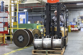
 The disc couplings used in this power plant application are inherently balanced. There is less vibration as they wear, and they perform a limited end float function without special design considerations for the sleeve bearings. The disc couplings used in this power plant application are inherently balanced. There is less vibration as they wear, and they perform a limited end float function without special design considerations for the sleeve bearings. |
Even the smallest component can play a crucial role in maintaining a consistent power supply. Consider, for instance, the case of a relatively small coupling at a leading coal-fired plant in the Midwest.
The plant had been experiencing gear coupling failure in its coal pulverizer drives. A coal pulverizer is critical equipment. If it’s not blowing coal, it’s not generating power and revenue is lost. Such plants can have up to 25 coal pulverizer drives, depending upon their size. Pulverizing coal results in less emissions and a more efficient use of the fuel. The heat generated is used to create steam that turns generators, providing electric power. Large electric motors drive the coal pulverizers by means of a worm gear arrangement, which also drives an exhauster fan that blows the pulverized coal to the furnaces. The shafts from the motor, worm gear and exhauster fan must be connected mechanically. This is where the relatively small yet vital coupling comes into play. If the coupling fails, the pulverizer can no longer operate. The original design of the power plant incorporated the use of gear-type couplings. This type of coupling allowed axial movement of the shafts, increasing the wear on the gears and other components such as the sleeve bearings in the motors. Eventually, these components fail prematurely. Loss of production due to downtime was an issue at the plant. Replacement costs were in the thousands per bearing. Preventive maintenance costs associated with gear couplings were becoming a burden due to time spent on inspection and lubrication to keep them operative. The power plant’s rigorous preventive maintenance program required regular disassembly of the gear couplings for inspection, cleaning and re-lubrication of the gear teeth. Visual inspection of the couplings was a judgment call, unless extensive, time-consuming measurements were performed. Additionally, heavy machinery was required to move the motors for coupling replacement.
Gear vs. Disc
A better solution was needed. The gear couplings, which were typical of the technology available when the plant was built in the early 1970s, did not limit axial movement of the motor shafts, and sleeve-type bearings were used in the motors. In fact, thermal growth of the shaft and the position of the shaft at magnetic center increased wear and shortened life spans of not only the motor sleeve bearings but also the gear couplings.
Increased sliding velocity of the gear teeth in the gear coupling creates a lot of heat and wear. It’s like rubbing two sticks together. The motor moves a bit, and the gear on the coupling moves a bit. This motion can be repeated up to a million times over the course of the day, contributing to premature failure. A possible solution would have been to install gear couplings with limited end float, but the maintenance issues associated with gear couplings would continue. Gear couplings are difficult to assess for wear and inspection, plus replacement of the gear coupling still requires removing the motors. Additionally, gear couplings still would have to be disassembled, inspected, cleaned and re-greased every time. Unwilling to compromise on maintenance costs, the plant manager decided to invest in disc couplings. Unlike gear couplings, they are inherently balanced. Thus, there is less vibration as they wear, and they perform a limited end float function without special design considerations for the sleeve bearings. Maintenance-free operation is achieved because the disc coupling has no moving parts and requires no lubrication. This translates into long coupling life.
Maintenance Power
Now preventive maintenance and inspection of the coupling’s flexible elements are possible using a simple strobe light, even while the pulverizer is running, instead of expensive shutdown and disassembly. Replacement of the disc packs can be done predictively and without moving any machinery or disturbing the original alignment.
Another bonus is a heavier duty coupling was provided for the same space allowed by the original design. Nothing had to be moved or modified for installation. Additionally, the component cost was comparable to that of a gear coupling. Not all disc couplings would have been suitable for this application. A disc coupling design that allows for more capacity and misalignment capability was needed. In this case, Lovejoy SX Disc couplings were used. Another benefit of these disc couplings is the maintenance staff can tell when one needs replacing. With a gear coupling, it’s a judgment call. Unless you take it off the machine and measure it extensively, you can’t tell visually if the gear teeth are acceptable. With the disc couplings, the outer leaf of the disc cracks before the entire coupling fails, signaling to the maintenance staff it needs replacing. Replacement simply involves replacing the disc pack.
Automatic segment termination to assure that local parts of a segment will continue to function if remote parts are accidentally disconnected. "The auto-terminator feature helped prevent any wiring errors; it's almost foolproof," says Gale. "Another big benefit of using these particular units is their circuit protection." While older generation device couplers employ "current-limiting" when a short occurs on the spur between the device and the coupler, the usual "lock-in" load is 60 mA, and no less. The danger of locking in this much current is the risk of causing other devices to receive insufficient current, in which case they drop off of the network. Whereas the MooreHawke device couplers utilize a fold-back technique which locks in a small 2 mA load - just enough to turn on an LED light - and then removes the device from the segment. Once the short is removed, the coupler automatically resets the device on the network. "The short circuit protection is a really good feature, notes Peters. \ldblquote It also helps the installation process go quicker." Once installed, modern device couplers can also improve the reliability of the control system through diagnostic capabilities in excess of what Fieldbus has to offer by itself. Each MooreHawke coupler, for instance, contains LED indicators to provide status checks at a glance. Intuitively, the red LED indicates a fault in the spur; green, an intact healthy spur. This status information extends to each spur, so for a 10-spur device coupler there would be 20 LEDs - a pair for each spur. Second generation device couplers further accelerate field commissioning and routine monitoring by providing easy access points for hand-held communicators such as Fieldbus trouble-shooting devices. Quick attachment of probes helps maintenance personnel track down any potential problems in the system.
Specifying Device Couplers That "Pay"
Currently, as much as 80 percent of all new plant control systems that utilize bus technology are Foundation Fieldbus compliant, and the trend is expected to continue. This adds increased importance to the device couplers that connect everything. With all the benefits they stand to offer, it pays for plant management to become involved in the specifying process to ensure that these new tools find their way into new plants, retrofits and expansions. "The key to any successful Fieldbus installation is up-front engineering," stresses Peters. "Get it designed well and it will pay off for you." "I can't quantify how much money it saved us, but it did save us time - and time is money," says Gale. "I also believe that the pricing on the MooreHawke device couplers was more competitive than others. In that case, it did save some hard dollars up-front."
}pted command is meant for the first controller, then the command is executed. If the command is meant for another component on the bus, the information is passed directly through CANopen to the appropriate device and then the command is executed.
Application Examples
Applications that can benefit from the use of controllers with CANopen communications interface capability include any automation system in any industrial operation that needs multiple local controls. An example is an automated welding machine that needs to have a central control system, which integrates with other parts of the manufacturing process, as well as a remote system that can control specific operations. Welding machine control often is the domain of PLCs. When adjusting and manipulating data necessary to control feed rates, as well as control the I/O of the system, a PLC easily integrates, through the use of CANopen, with the controller’s digital positioning system. Multiple axes of control are instantly attainable.
Another example of how the controller can be incorporated into a CANopen communications system is when a packaging device requires a precise ratio between two axes. The PLC can maintain overall system operation without affecting the axes directly. A controller with CANopen communications interface capability is ideal for such an operation. CANopen can easily be engaged to communicate directly with the controller. This allows the controller to handle the precise ratio requirements of the system, while the PLC maintains communications contact with the other devices in the system.
Structure and Protocol
Transferring data is done using a system that reads and writes to the controller’s object dictionary. Service Data Object (SDO) transport protocol is the entry used to transmit these objects, regardless of size. The SDO communication is used to configure the object of the controller. Although larger entries are split into segments, segmenting isn’t necessary for objects of four bytes or fewer; as a result, transfer can be expedited. Nearly all objects in the controller’s object dictionary are designed to be non-segmented transfers to ensure speed.
Higher priority transfers are also possible when dealing with the need for real-time data. This is done using Process Data Objects (PDOs), which are unconfirmed services containing no protocol overhead. Consequently, they represent an extremely fast and flexible method of transmitting data from one node to any number of other nodes. PDOs can be specifically compiled and confirmed by the user to suit specific requirements. Each PDO has a unique identifier and is transmitted by only one node. But it can be received by more than one producer/consumer communication. PDO transmissions may be driven by remote requests and by sync messages received. A remotely requested trigger is when another device initiates the transmission of an asynchronous PDO by sending a transmission request. For synchronous transmission triggering, in order to initiate simultaneous sampling of input values of all nodes, a periodically transmitted sync message is used. Synchronous transmission of PDOs can take place in cyclic and acyclic transmission modes. Multiple digital positioning controllers can be used to alleviate specific and/or critical operations from the central PLC control, desktop computer system or proprietary controller.