Laser cutting techniques helped speed robotics prototyping for the Stanford BioRobotics Lab, a group that set itself the task of developing a "personal robot" that can operate in a home-type environment and have sufficient dexterity to perform basic household tasks.
|
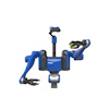
Personal Robot Pr-1 Prototype |
The Stanford BioRobotics Lab is a university research group involved in the development of robots primarily for medical and industrial applications.
In 2006, our group set itself the task of developing a “personal robot;” that is, a robot that can operate in a home-type environment and have sufficient dexterity to perform some basic household tasks, such as opening a refrigerator door and retrieving an item from inside. Another design imperative was to address the issue of human safety, that is, to work in the human environment and around humans without causing harm.
The extreme mechanical complexity of this system necessitated numerous prototype cycles, and our group quickly discovered that using outside fabrication resources was both excessively time consuming and cost prohibitive.
To remedy this, we acquired a CO2 laser based cutting system which then enabled us to rapidly prototype parts from a variety of materials, including plywood, aluminum, steel and various plastics. This article reviews the design concept of the personal robot project, and explores how the rapid prototyping capabilities of the laser cutting system were critical in successfully achieving these.
The Personal Robot
The goal of the personal robot program was to develop robust and safe robots that do real tasks for humans like performing household cleaning, retrieving items, carrying heavy loads, handling laundry and preparing food. To achieve these ends, the robot was intended to move over the surfaces commonly encountered in the home, and to negotiate slightly uneven surfaces and transitions, such as door jambs and power cords, without difficulty.
The robot was also designed to go up 8° grades (such as wheelchair ramps), but not to climb stairs. To achieve these ends, the robot was conceived to have a base mounted on pneumatic tires which moves with two degrees of freedom. This omni-directional base supports the robot torso and enables it to rotate.
|
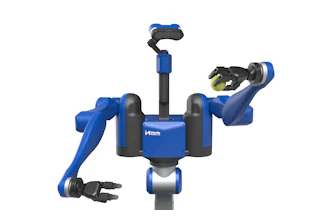
PR-1 arm kinematics |
In order to handle and interact with various household items (e.g. tools, appliances, containers, etc.), the robot was also envisioned to have two arms, with somewhat similar size, strength and dexterity characteristics to human arms, and terminated with simple hands. This requirement poses a significant engineering challenge, since the payload ratio (payload weight/manipulator weight) for human-sized industrial robots is typically on the order of 1:10, while the human arm ratio is about 1:1.
As designed, each of the arms has seven degrees of freedom: pan, tilt and rotation of the shoulder joint, elbow flexion, forearm rotation and wrist flexion and rotation. The arms can lift loads of up to 5 kg. To achieve this combination of motion and payload capacity while still ensuring safety, a clever gravity compensation system was utilized. This system comprises a combination of compression springs, highly geared, small motors and steel timing belts within the arms to passively float the arm and payload throughout the entire movement range.
The benefit of this approach is that it reduces the need for large motors in the arms, and enables the use of back-drivable transmissions. The latter is particularly important for ensuring both human and robot safety in unstructured, real world environments.
The basic design approach for these arms was to locate the upper segment and elbow drive motors as close to the shoulder joints as possible, and then use drive belts to deliver the motion over a distance. This was done in order to keep the weight distribution towards the shoulder, and thus minimize the net torque required for motion and reduce the chance that the arm will damage something that it hits accidentally. And finally, the use of drive belts was preferred over gears because belts systems can be constructed to have essentially no backlash.
Practical Prototyping
When designing a system of this complexity, it’s often difficult to envision in advance all the issues that may occur with mechanical interference between various system components, or to calculate exactly how loads will be transferred through joints. Thus, there’s no substitute for building a working prototype. However, the construction parameters (strength of materials, etc.) of the prototype must be close enough to the final build form to reliably predict its properties.
Of course, the most straightforward solution is to simply construct prototype parts out of the final form materials and assemble them.
Unfortunately, this approach is also the most costly and time consuming, especially if outside fabrication resources are used. And, for a complex system, which may require multiple design, prototype and revision cycles, these limitations are compounded. This was just the situation that the Stanford BioRobotics Lab faced in building the personal robot, compounded by the budget constraints of a university research department.
For our group at Stanford, we did have some alternatives in place when this program began sending out parts to traditional machine shops. For example, we possess a CNC milling system, which is capable of fabricating a wide range of parts of metal, plastics and wood. However, the setup time to produce a part on this system is typically several hours. Furthermore, because of the complexity of the machine’s user interface, not everyone in our lab is trained to use the equipment. Because of these difficulties, we simply don’t use the CNC system that much.
We also have a 3D printer in our lab. While this system is easy to use in terms of the operator interface and required setup time, it does have two significant drawbacks for our particular requirements. First, the more economical materials normally utilized for 3D printing don’t have sufficient mechanical strength for our prototyping needs. For example, we can’t press fit a bearing into the typical 3D printer produced part. The second problem with 3D printing is that it generally doesn’t deliver the resolution and dimensional accuracy we require.
To meet our ongoing needs for rapid prototyping, we acquired a laser cutting system. The Coherent BEAM Laser Machining Center we obtained mates a 500W CO2 cutting laser with a motion system, (enabling it to process items of up to about 1.25" in thickness, depending upon material) over a 4′ x 4′ working area.
|
Coherent BEAM Laser Machining Center |
Depending upon the material, the system can cut to a dimensional precision of up to 0.001" (0.0002" repeatability), at speeds up to 2,000 inches/min. And it’s very helpful that the operator interface is similar to a 3D printer. Namely, part drawings are created in SolidWorks or some other application that produces files in DXF, DWG, AI, HPGL, Gerber, JPG, BMP or TIF format. These are simply sent to the cutting system through the software’s print command.
The cutting characteristics of the CO2 laser are an especially good match for our prototyping needs. Specifically, the mid-infrared output of the laser is well absorbed by a wide range of materials including plastics, paper, films and carbon fiber, and the raw power of the laser permits cutting of thin metals as well. Plus the ability to precisely control cutting parameters enables the system to work in many modes, such as cutting, scoring, perforating and engraving.
Laser Cutting in Practice
|
Early PR-1 concept, prototyped in plywood |
The photo shows a segment of a prototype robot arm fabricated from plywood. Typically we build up 3D structures from ¼" thick plywood pieces; this material provides excellent stiffness and strength for our purposes, and is readily cut to the required accuracy with the Coherent system.
We often use mortise and tenon construction, combined with dowel pins, epoxy cement and wood screws for attachment, and this yields structures with the needed strength to weight ratio. Plywood is also a strong enough material to allow us to press fit in a metal bearing, and the laser cutter can produce holes with the necessary tolerances for press fits. It also delivers the precision required to produce correct tooth profiles for the gears and belt drive-pulleys. In terms of metals, we often use the laser system to cut 0.040" thick aluminum for motor mounts, and sometimes process thin steel (in the 1/16" to 1/8" range) to produce higher strength parts.
In addition, the flexibility and accuracy of the laser cutter makes it useful for a variety of other tasks around the lab. For example, we can cut 0.005" thick steel to make templates for PCB fabrication. We can also cut very thin materials, such as films or paper, which would be impossible to process in a mill because they are too delicate to be clamped.
Conclusion
The long term goal of the personal robot project was to develop a platform that other research groups could build upon. Our in house, rapid prototyping capabilities were key in enabling us to accomplish this with our PR-1 personal robot. Now, we’ve partnered with Willow Garage, who have taken our original design ideas and refined them further. Their PR2 robot, constructed from metal, is currently available to other facilities and a growing community of researchers, who are now able to collaborate using a standard platform.
For more information visit http://biorobotics.stanford.edu.