Factory automation is extending from production operations to quality control (QC) operations, both on the manufacturing floor and in the QC lab.
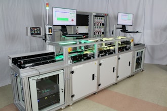
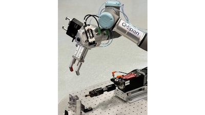
The Q-Span Automated Gauging System uses a collaborative robot to pick parts from a part presentation location, take measurements using a variety of gauges and place parts in a drop-off location. It collects and consolidates data from all gauges in the system and can be used for real-time decision-making, QC documentation and statistical analysis.
The automated gauging system can perform in-process inspection at a machine output or in an inspection cell. Machined, molded or extruded parts can be measured. The system can separate good/bad parts or grade and sort them into any number of locations, based on any measured dimension. Good parts are ready to be sent on to the next process; bad parts are sent to rework or scrap.
In-process gauging data from the Q-Span System can also be used to make machine adjustments in real time, such as changing tool offsets to compensate for tool wear in a CNC mill or lathe. This supports “lights out” operation and this tighter process control can nearly eliminate scrap and waste.
Here are the top five manual gauge measurements that manufacturers are automating using the Q-Span System. The first four involve using a collaborative robot to move a part to a fixture and activating a standard mechanical gauge.
Because this approach automates the manufacturer’s existing gauges and/or gauging techniques, re-validating the gauges is not necessary and you can expect improvements in gage repeatability and reproducibility (GR&R) because the robot removes human error from the gauging process.
1. Micrometer or Height Gauge Measurements
Q-Span System uses a drop gauge or linear probe (LVDT) to automate measurements previously made with manual micrometers or height gauges. These linear digital contact sensors are mounted on the workstation table, within a measurement fixture.
The collaborative robot, using a suitable part handling gripper, picks a part to be measured from the input location and places it in the fixture. The Q-Span system activates the linear probe and captures the resulting measurement data.
This gauge can be used to measure the height or thickness of a part. These linear probes vary in travel range and resolution, with resolution down to 0.1 μm and indicated accuracy of 1 μm and measuring ranges from 1 mm to 50 mm or more (0.04” to 1.97").
Selecting the most appropriate probe depends on your part dimensions, tolerances and optimizing the system for maximum flexibility as additional parts are programed for inspection within the system. Probe tips can be easily customized and optimized for both the geometries of the part’s inspected feature and materials for highly regulated industries and use cases.
2. Go/No-Go Thread Gauging
Threads are time consuming and labor intensive, often requiring machinists or inspectors to manually turn both a go and no-go thread plug in and out of the part. This can take anywhere from 5 seconds to minutes per part.
Automation requires the robot arm to simply load threaded parts into a fixture and activate a motorized thread gauge to mechanically verify threaded holes or externally threaded features.
The Q-Span System can sort parts based on measured data, such as thread depth of blind holes or reject parts for defects such as missing, short or improperly formed threads. Systems can be configured with two separate “GO” and “NO-GO” thread tests, a combination thread plug that includes both a go and no-go verification on the same thread plug or even thread chasing and remediation.
3. Manual Bore Gauge or Air Gauge
To measure an inner diameter, the workstation uses a robotic gripper to load parts onto a bore gauge or air gauge that is mounted on the workstation table. With these gauges, the measuring head is customized to the part being measured, with as little as 0.001 inch clearance between the measuring head and the part.
The Q-Span System’s collaborative robot has position resolution and repeatability that matches or exceeds the dexterity of human operator, allowing it to reliably automate part insertion and removal on these gauges.
The system activates the gauge and collects the resulting data, then the part is removed and moved on to the next QC check or process step.
Recessed features, inside an inner diameter, are often unreachable using a standard bore gauge. A robotic caliper (see below), mounted on the robot arm and fitted with appropriate probe tips, such as semi-spherical disc styli, can be used to reach these recessed features, automatically rotating to take multiple measurements around the inner diameter.
4. Many manual gauges – 2D Optical Profiler
When many simple measurements are required on external part features and especially when minimizing inspection cycle times are a critical application requirement, it may be more practical to use a vision system, such as a 2-dimensional optical profiler.
These systems include a transmitter and receiver, displaying a 2D silhouette of the part, allowing you to measure dozens of part features in milliseconds with measurement accuracy as low as +/- 0.2 μm to +/- 2.5 μm.
These 2D profilers can also be more practical when measuring external threads, relative positional measurements or angles of external features. If multiple measurements are needed, such as when the minimum and maximum dimension must be captured, the part can be simply presented to the 2D profiler by the robot and rotated through the gauge to capture the min/max values very quickly, while minimizing the mechanical wear you would see from a mechanical gauge.
The drawback of vision systems are typically integration complexity and cost. The list price for these systems is relatively high, compared to our aforementioned mechanical gauges, but in the long-term, the system may be less expensive because the non-contact measurements add flexibility when redeploying the gauge for many different parts, without having to buy and integrate more mechanical gauges each time a new part must be automated.
The advantage of 2D profilers over many 3D vision systems is that the silhouette-based measurements are much simpler than 3D vision. Additionally, modern software packages allow for very easy programming to minimize the complexity of integration.
5. Manual Caliper Measurements
For automated caliper measurements, a robotic caliper is mounted on the robot arm. These gripper/calipers can be used for both part handling and as an inspection tool. These robotic calipers can be opened or closed to measure inner diameters, outer diameters, dovetail features, recessed features and more.
The robotic caliper in the Q-Span System has a measurement resolution of 2.5 µm (0.0001”).
Flexible Automation for QC in High-Mix Manufacturing
Collaborative robots are making QC automation accessible to small and mid-size manufacturing operations because they are faster to implement, with lower capital expense than traditional industrial robots and offers greater flexibility to perform the multiple functions needed in high-mix manufacturing.

