Working to minimize corrosion continues to be a major problem in the lubricant industry. The greater use of multiple metals in applications makes the situation worse as lubricant suppliers must now deal with greater instances of multi-metal corrosion.
As an example, aluminum — due to its lighter weight than steel — is being used in more applications. In a previous TLT article, the preparation of an inorganic coating based on silica was described that is very useful in protecting aluminum surfaces from corrosion caused by exposure to sunlight in aqueous environments. This ultraviolet light-resistant coating is particularly suitable to protect aluminum surfaces used on ships.
A way to help this effort in developing better corrosion inhibitors is to develop a technique for actually obtaining a visual image of how corrosion is initiated at the molecular level. One type of corrosion that is very relevant is crevice corrosion where complex electro-chemical reactions can take place in tiny cracks (crevices).
With lubricants working to function at times in very confined spaces where adjacent surfaces are in close proximity to each other, crevice corrosion can hinder machinery performance. Jacob Israelachvili, research professor emeritus in the materials department and the department of chemical engineering at the University of California, Santa Barbara, says, “Working in confined spaces can be very difficult where there are two surfaces that are only a few nanometers apart. One of the surfaces may be a conducting metal while the other may be nonconducting. Or the two surfaces may be of the same conducting material but where the differential stresses on either side of a crack generates an electric potential difference (voltage) between the two surfaces, which is one of the main driving forces for corrosion.”
Crevice corrosion is typically initiated by the formation of small circular pits in an aqueous environment that can vary in size and shape. These pits are formed due to metal ions that dissolve in the water that then become concentrated within the crack. This movement of ions between the two different surfaces of the crack can create or alter the potential difference that impacts the flow of anions into and cations out of the crevice, resulting in further “pitting corrosion” and dissolution.
Visualizing crevice corrosion in real time is difficult according to Israelachvili. He says, “Being able to see and resolve what is happening in real time in a very small (submicroscopic) gap is a challenge particularly because the pits form in an anisotropic fashion at an extremely fast rate. The pits then slowly grow and eventually coalesce.”
Observing crevice corrosion in real time would be an invaluable tool for helping to determine the origin of this type of corrosion and for developing ways to control or minimize it. Such a technique is now available.
Electrochemical Surface Forces Apparatus
Israelachvili’s research group and colleagues from professor Markus Valtiner’s group at the Max-Planck-Institut für Eisenforschung in Düsseldorf, Germany, used an instrument known as an electrochemical surface forces apparatus (EC-SFA) to literally watch as crevice corrosion initiated and propagated in a circular-shaped crevice with about a 300-micron diameter. Israelachvili says, “The SFA has been used for a long time to measure forces (such as friction, adhesion and van der Waals forces) between surfaces at the ångstrom resolution level (1Å = 0.1 nm = 1/108 cm). We modified a conventional SFA by including a means to also measure and control the electric voltage and/or current between the two surfaces.” The researchers initially pressed mica and nickel surfaces together to form the crevice in the absence of any fluid. Then an electrolyte was added at varying concentrations, and the electrochemical potential was then increased to generate the corrosion. All of the corrosion images were recorded using an optical camera that produced a real-time video. Pit growth measurements were recorded down to the angstrom level.
Nickel was chosen as the conducting metal because it is widely used in marine applications. Israelachvili says, “Mica was selected as the nonconducting surface because it is transparent, chemically inert and forms a thin sheet with atomically smooth surfaces.”
Sodium chloride was chosen in part as the electrolyte because it is a common salt. Israelachvili says, “We know that chloride is very prevalent in marine environments and is a major contributor to crevice corrosion.”
Chloride anions tend to migrate into the crevice while cations (e.g., Ni2+) formed as the metal surface dissolves leave the crevice. This can reduce the pH within the crevice further accelerating the corrosion process.
In monitoring corrosion, the researchers looked at and recorded colored fringes (known as multiple beam interference fringes). Israelachvili says, “We evaluated changes in the color, shape, spectral position and intensity (brightness) of the fringes. When the metal surface started to corrode, the surfaces became very bright in those places where new pits suddenly appeared in an analogous fashion to exploding stars.”
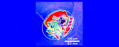
 Figure 1. A crack junction showing crevice corrosion is shown. The bright white images are areas of corrosion where pits are growing and coalescing. (Figure courtesy of the University of California, Santa Barbara.)
A visual image showing crevice corrosion at a crack junction with a diameter of about 200 microns is shown in Figure 1. The two surfaces are within one to three nanometers of each other. Areas of corrosion are characterized by the bright white images showing the growing and coalescing pits.
 Dr. Neil Canter
The researchers indicate that corrosion pits typically form initially along high edges of the metal surface where there is a higher potential. The diameter of the pits are originally six to seven microns with a depth of seven to eight nanometers.
The mechanism of crevice corrosion will be considered in the next phase of the project. Israelachvili says, “We need to have modeling done to determine how the pits initially form leading to the start of crevice corrosion.”
Reprinted with permission from the December 2017 issue of TLT, the monthly magazine of the Society of Tribologists and Lubrication Engineers, an international not-for-profit professional society headquartered in Park Ridge, Il. Dr. Neil Canter is a contributing editor of TLT Tech Best. He heads his own consulting company, Chemical Solutions, in Willow Grove, Pa.